状态机设计:
(1)一组触发器的输出状态随着时钟和输入信号按照一定规律变化的一种机制或过程。
(2)一类十分重要的时序电路。
(3)许多数字电路的核心部件。
(4)任何时序电路都可以表示为有限状态机。
(5)状态的转换:下一个状态由译码器根据当前状态和输入条件决定。
(6)输出信号的产生:输出信号由译码器根据当前状态和输入条件决定。
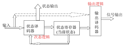
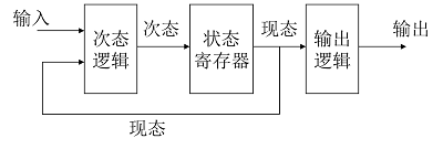
状态机的结构
组合逻辑部分
状态译码器(次态逻辑):确定状态机的下一个状态。
输出译码器(输出逻辑):确定状态机的输出。
寄存器部分
状态寄存器(内部状态):存储状态机的内部状态下一个状态不仅与输入信号有关,而且还与该寄存器的当前状态有关。
同步时序状态机:由时钟信号触发状态的转换和信号的输出。大多数可综合的状态机设计要求使用同步状态机。
异步时序状态机:状态的转移和输出不与时钟信号同步。
分类:
结构上:单进程状态机和多进程状态机。

编码方式:顺序编码、一维热码、其他编码。

输出的产生:Moore型、Mealy型。
状态机的设计
四部分:
(1)说明部分
状态名定义:用type语句定义数据类型,元素为枚举型。
状态变量:定义为信号,便于信息传递。
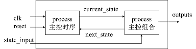
(2)主控时序进程
负责状态机的运转,时钟驱动下负责状态转换。
(3)主控组合进程
根据外部控制信号和当前状态值,确定下一个状态。
根据对内、外输出控制信号的内容。
(4)辅助进程:配合状态机工作的组合进程或时序进程。
--双进程状态机
LIBRARY IEEE;
USE IEEE.STD_LOGIC_1164.ALL;
ENTITY state_machine IS
   PORT(reset, clk, x : IN STD_LOGIC;
				z : OUT STD_LOGIC);
END state_machine;
ARCHITECTURE beh OF state_machine IS
type statetype is (state0, state1);
signal state, next_state: statetype := state0;
BEGIN
   comb_process: process(state, x)
   begin
       -- describtion here
   end process comb_process;
   clk_process: process(clk)
   begin
       -- describtion here
   end process clk_process;
END beh;
组合逻辑部分:下一状态与输出的计算。
comb_process: process (state, x)
Begin
case state is
   when state0 =>
if x = ‘0’ then
    next_state <= state1; z <= ‘1’;
else
    next_state <= state0; z <= ‘0’;
end if;
   when state1 =>
if x = ‘1’ then
     next_state <= state0;z <= ‘0’;
else
     next_state <= state1;z <= ‘1’;
end if;
end case;
end process comb_process;
Clock进程:采用一个同步复位来将状态机初始化到一个已知的状态。
clk_process: process(clk)
    begin
         wait until (clk’event and clk = ‘1’); -- wait until the rising edge
         if reset = ‘1’ then -- check for reset and initialize state
            state <= statetype'left;
        else
            state <= next_state;
        end if;
    end process clk_process;
end behavioral;
Moore型状态机的设计
Mooer状态机的输出只与当前的状态有关,也就是当前的状态决定输出,而与此时的输入无关,输入只决定状态机的状态改变,不影响电路最终的输出。
以存储控制器状态机的设计为例:
要求:
根据微处理器的读、写周期,分别对存储器输出两种信号
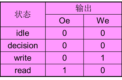
写使能:We
读使能:Oe
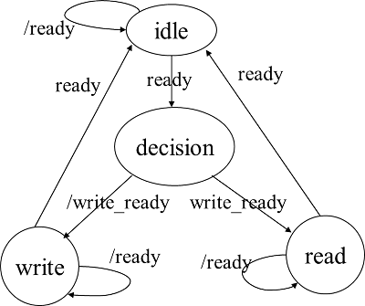
工作过程:
存储控制器的输入信号:
就绪:ready
读写:read_write
上电复位或ready有效
存储控制器开始工作,并在下一个时钟周期判断read_write信号,决定下次作业是读(Oe有效)还是写(We有效)
ready有效;
本次作业处理完成,恢复初始状态。
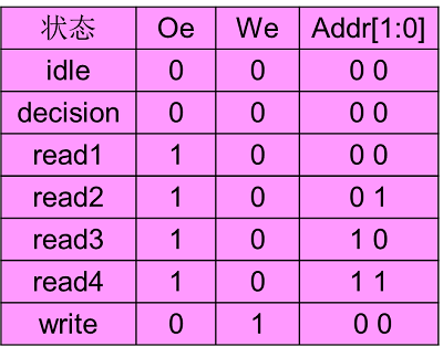
存储控制器各状态输出:
状态转移图:
LIBRARY IEEE;
USE IEEE.STD_LOGIC_1164.ALL;
ENTITY state_machine IS
   PORT(reset, clk, x : IN STD_LOGIC;
                               z : OUT STD_LOGIC);
END state_machine;

ARCHITECTURE beh OF state_machine IS
    type statetype is (idle, decision, read, write);
    signal present_state, next_state: statetype := idle;
BEGIN
   comb_process: process(present_state, x)
     ---
   clk_process: process(clk)
     ---
END beh;
组合逻辑部分:
comb_process: process (present_state, read_write, ready)
Begin
case present_state is
   when idle => oe<=<'0'; we<=<'0';
if ready ='1' then
    next_state <= decision;
else
    next_state <= idle;
end if;
   when decision => oe<='0'; we<='0';
       if read_write = '1' then
     next_state <= read;
else
     next_state <= write;
end if;
when read => oe=<'1'; we=<'0';
if ready ='1' then
    next_state <= idle;
else
    next_state <= read;
end if;
    when write => oe=<'0'; we=<'1';
if ready ='1' then
    next_state <= idle;
else
    next_state <= write;
end if;
end case;
end process comb_process;
Clock进程:
clk_process: process(clk)
    begin
         wait until (clk’event and clk = ‘1’); -- wait until the rising edge
         if reset = ‘1’ then -- check for reset and initialize state
            present_state <= statetype’left;
        else
           present_state <= next_state;
        end if;
    end process clk_process;
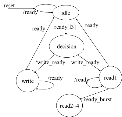
状态机复位:
以SRAM存储控制器为例。使用时,首先输出总线标识F3(hex),在下一周期输出读写信号, read_write信号高电平。
读SRAM:
  burst信号为低,单字节读
  burst信号为高,4字节猝发
  在连续读期间Oe有效,地址线依次递增,以便使SRAM输出地址连续,并能依次读四个连续地址内的数据
写SRAM:
  单字节方式,写信号We有效时将数据写入到SRAM指定地址。
ready信号有效时,标志读、写操作完成。
SRAM存储控制器,需要复位信号reset,需随时判断该信号是否有效。
方案一:
comb_process: process (reset, present_state, burst, read_write, ready)
Begin
   if (reset='1') then
	  --由于隐含存储效应(保持原来的值),需指定复位值。
      oe<='0'; we<='0'; addr<='00';
      next_state=idle;
   else
      case present_state is
       --
      end case;
   end if;
end process comb_process;
方案二:
comb_process: process (reset, present_state, burst, read_write, ready)
Begin
   case present_state is
       --
   end case;
   if (reset='1') then
	  --由于隐含存储效应,需指定复位值
      next_state=idle;
      oe<='0'; we<='0'; addr<='00';
   end if;
end process comb_process;
SRAM存储控制器的同步复位双进程状态机:
LIBRARY IEEE;
USE IEEE.STD_LOGIC_1164.ALL;
ENTITY memory_controller IS
   PORT(reset, read_write, ready, burst, clk: IN STD_LOGIC;
               bus_id   : IN STD_LOGIC_VECTOR(7 DOWNTO 0);
               Oe, We : OUT STD_LOGIC;
                addr     : OUT STD_LOGIC_VECTOR(1 DOWNTO 0));
END memory_controller;

ARCHITECTURE beh OF memory_controller IS
   type statetype is (idle, decision, read1, read2, read3, read4, write);
   signal present_state, next_state: statetype := idle;
BEGIN
   comb_process: process(reset, bus_id, present_state, burst, read_write, ready)
     ---
   clk_process: process(clk)
     ---
END beh;
组合逻辑部分:
comb_process: process(reset, bus_id, present_state, burst, read_write, ready)
Begin
   if (reset='1') then
      oe<='0'; we<='0'; addr<='00';
      next_state=idle;
   else
     case present_state is
   	  when idle => oe<='0';we<='0';addr<="00";
		if bus_id ="11110011" then
    	  next_state <= decision;
		else
    	  next_state <= idle;
		end if;
   	  when decision => oe<='0'; we<='0';addr<="00";
        if read_write = '1' then
     	  next_state <= read1;
	    else
          next_state <= write;
        end if;
      when read1 => oe<='1'; we<='0';addr<="00";
        if ready ='0' then
          next_state <= read1;
        elsif burst='0' then
          next_state=idle;
        else
          next_state <= read2;
        end if;
      when read2 => oe<='1'; we<='0';addr<="01";
        if ready ='0' then
          next_state <= read2;
        else
          next_state <= read3;
        end if;
      when read3 => oe<='1'; we<='0';addr<="10";
        if ready ='0' then
          next_state <= read3;
        else
          next_state <= read4;
        end if;
      when read4 => oe<='1'; we<='0';addr<="11";
        if ready ='0' then
          next_state <= read4;
        else
          next_state <= idle;
        end if;
      when write => oe<='0'; we<='1';addr<="00";
        if ready ='1' then
          next_state <= idle;
        else
          next_state <= write;
        end if;
     end case;
end process comb_process;
Clock进程(触发器实现):
clk_process: process(clk)
    begin
         if (clk'event and clk = '1') then
              present_state <= next_state;
		-- 下一状态时钟同步赋值
        end if;
    end process clk_process;
异步复位适用于上电复位,系统错误复位,占用资源较多。
clk_process: process(clk, reset)
    begin
        if reset = '1' then -- check for reset and initialize state
              present_state <= idle;
        elsif (clk'event and clk = '1') then
              present_state <= next_state;
        end if;
    end process clk_process;
单进程状态机设计:
LIBRARY IEEE;
USE IEEE.STD_LOGIC_1164.ALL;
ENTITY memory_controller IS
   PORT(reset, read_write, ready, burst, clk: IN STD_LOGIC;
               bus_id   : IN STD_LOGIC_VECTOR(7 DOWNTO 0);
               Oe, We : OUT STD_LOGIC;
                addr     : OUT STD_LOGIC_VECTOR(1 DOWNTO 0));
END memory_controller;

ARCHITECTURE beh OF memory_controller IS
   type statetype is (idle, decision, read1, read2, read3, read4, write);
   signal state: statetype;
BEGIN
   state_tr: process(reset, clk)
     ---
END beh;

state_tr: process(reset, clk)
Begin
   if (reset='1') then
      state=idle;
   elsif (clk'event and clk = '1') then
      case state is
   when idle =>
if bus_id ="11110011" then
    state <= decision;
else
    state <= idle;
end if;
   when decision =>
       if read_write = '1' then
    state <= read1;
else
    state <= write;
end if;

when read1 =>
       if ready ='0' then
    state <= read1;
elsif burst='0' then
    state=idle;
else
    state <= read2;
end if;
    when read2 =>
       if ready ='0' then
    state <= read2;
else
    state <= read3;
end if;
    when read3 =>
       if ready ='0' then
    state <= read3;
else
    state <= read4;
end if;
    when read4 =>
       if ready ='0' then
    state <= read4;
else
    state <= idle;
end if;

 when write =>
   if ready ='1' then
      state <= idle;
   else
      state <= write;
   end if;
     end case;
   end if;
 end process state_tr;
    with state select
             oe=<='1'  when read1|read2|read3|read4,
                        '0'  when others;
    with state select
             we=<'1'  when write,
                      '0'  when others;
    with state select
             addr<="01"  when read2,
                        "10"   when read3,
                        "11"   when read4,
                         "00"  when others;
end beh;
moore型状态机的状态编码和信号输出方法:
顺序编码(符号化)
	组合译码输出
	并行译码输出
状态直接编码输出
一位有效编码方式
顺序编码:方式最简单,触发器数量最少,非法状态最少,容错技术最简单。但增加了状态之间转换的译码组合逻辑。输出的控制信号,如Oe、We等还需要一个组合进程作为控制译码器。
组合译码输出:oe、we、addr由状态位译码得到,多经过一级逻辑,在时钟上升沿之后才能到达输出端口,因此延迟较大
with state select
             oe=<='1'  when read1|read2|read3|read4,
                        '0'  when others;
    with state select
             we=<'1'  when write,
                     '0'  when others;
    with state select
             addr<="01"  when read2,
                        "10"   when read3,
                        "11"   when read4,
                         "00"  when others;
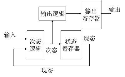
并行译码输出:增加了一个输出寄存器,缩短了延迟,占用了资源。
LIBRARY IEEE;
USE IEEE.STD_LOGIC_1164.ALL;
ENTITY memory_controller IS
   PORT(reset, read_write, ready, burst, clk: IN STD_LOGIC;
               bus_id   : IN STD_LOGIC_VECTOR(7 DOWNTO 0);
               Oe, We : OUT STD_LOGIC;
                addr     : OUT STD_LOGIC_VECTOR(1 DOWNTO 0));
END memory_controller;
ARCHITECTURE beh OF memory_controller IS
   type statetype is (idle, decision, read1, read2, read3, read4, write);
   signal present_state, next_state: statetype;
   signal addr_d: std_logic_vector(1 downto 0);  -- 新增信号
BEGIN
   state_comb: process(reset, bus_id, present_state, burst, read_write, ready)
   with next_state select
             addr_d<="01"   when read2,
                             "10"   when read3,
                             "11"   when read4,
                             "00"   when others;
  clk_process: process(clk, reset)
END beh;
组合逻辑部分:
comb_process: process(reset, bus_id, present_state, burst, read_write, ready)
Begin
      case present_state is
   when idle => oe<='0'; we<='0';
if bus_id ="11110011" then
   next_state <= decision;
else
   next_state <= idle;
end if;
   when decision => oe<='0'; we<='0';
       if read_write = '1' then
           next_state <= read1;
else
    next_state <= write;
end if;
   when read1 => oe<='1'; we<='0';
       if ready ='0' then     next_state <= read1;
elsif burst='0' then    next_state=idle;
else                          next_state <= read2;
end if;
    when read2 => oe<='1'; we<='0';
       if ready ='0' then   next_state <= read2;
else                        next_state <= read3;
end if;
    when read3 => oe<='1'; we<='0';
       if ready ='0' then    next_state <= read3;
else     next_state <= read4;
end if;
    when read4 => oe<='1'; we<='0';
       if ready ='0' then    next_state <= read4;
else     next_state <= idle;
end if;
    when write => oe<='0'; we<='1';
if ready ='1' then      next_state <= idle;
else       next_state <= write;
end if;
     end case;
end process comb_process;
Clock进程:
clk_process: process(clk, reset)
begin
    if reset='1' then
        present_state<=idle;
        addr<="00";
    elsif (clk'event and clk = '1') then
        addr<=addr_d;
        present_state <= next_state;
    end if;
end process clk_process;
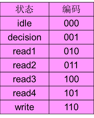
状态直接编码输出:
3位、7态编码 -> 5位、7态编码
LIBRARY IEEE;
USE IEEE.STD_LOGIC_1164.ALL;
ENTITY memory_controller IS
   PORT(reset, read_write, ready, burst, clk: IN STD_LOGIC;
               bus_id   : IN STD_LOGIC_VECTOR(7 DOWNTO 0);
               Oe, We : OUT STD_LOGIC;
                addr     : OUT STD_LOGIC_VECTOR(1 DOWNTO 0));
END memory_controller;

ARCHITECTURE beh OF memory_controller IS
   signal state: std_logic_vector(4 downto 0);
   constant idle: std_logic_vector(4 downto 0) := "00000" ;
   constant decision: std_logic_vector(4 downto 0) := "00001" ;
   constant read1: std_logic_vector(4 downto 0) := "00100" ;
   constant read2: std_logic_vector(4 downto 0) := "01100" ;
   constant read3: std_logic_vector(4 downto 0) := "10100" ;
   constant read4: std_logic_vector(4 downto 0) := "11100" ;
   constant write:  std_logic_vector(4 downto 0) := "00010" ;
BEGIN
   state_rt: process(reset, clk)
     ---
   end process state_rt;
   we<=state(1);
   oe<=state(2);
   addr<=state(4 downto 3);
END beh;
state_tr: process(reset, clk)
Begin
   if (reset='1') then
      state=idle;
   elsif (clk'event and clk = '1') then
      case state is
   when idle =>if bus_id ="11110011" then  state <= decision;
   else     state <= idle;
   end if;
   when decision =>if read_write = '1' then    state <= read1;
   else     state <= write;
   end if;
   	when read1 =>if ready ='0' then    state <= read1;
elsif burst='0' then     state=idle;
else     state <= read2;
end if;
    when read2 =>if ready ='0' then    state <= read2;
else     state <= read3;
end if;
    when read3 =>if ready ='0' then    state <= read3;
else     state <= read4;
end if;
    when read4 =>if ready ='0' then    state <= read4;
else     state <= idle;
end if;
    when write =>if ready ='1' then      state <= idle;
   else       state <= write;
   end if;
    when others =>state <= write;
      end case;
   end if;
end process state_tr;
一位有效编码方式:用N个触发器来表示具有N个状态的状态机,每个触发器表示一种状态。大大简化了状态译码逻辑,提高了转换速度。不依赖于时钟的同步,属于异步时序的概念。
Mealy型状态机
输出是现态和输入信号的函数。一旦输入信号或状态发生变化,输出信号即刻变化,因此与Moore型状态机相比,Mealy型状态机的输出变化要领先一个周期。
其VHDL结构要求至少两个进程,或一个状态进程加一个独立的并行赋值语句。
LIBRARY IEEE;
USE IEEE.STD_LOGIC_1164.ALL;
ENTITY mealy_controller IS
   PORT(clk, datain, reset: IN STD_LOGIC;
               q  : out STD_LOGIC_VECTOR(4 DOWNTO 0));
END mealy;
ARCHITECTURE beh OF mealy IS
   type states is (st0, st1, st2, st3, st4);
   signal stx : states;
   signal q1 : STD_LOGIC_VECTOR(4 DOWNTO 0);
begin
   comreg : process(clk, reset)    -- 决定状态转换的进程
     ---
   end process comreg;
   com1 : process(stx, datain, clk)  -- 输出控制信号的进程
     ---
   end process com1;
   q<=q1;
END beh;
决定状态转换的进程:
comreg : process(clk, reset)
Begin
   if reset='1' then stx<=st0;
   elsif clk'event and clk='1' then
       case stx is
     when st0 => if datain ='1' then  stx <= st1; end if;
     when st1 => if datain ='0' then  stx <= st2; end if;
     when st2 => if datain ='1' then  stx <= st3; end if;
     when st3 => if datain ='0' then  stx <= st4; end if;
     when st4 => if datain ='1' then  stx <= st0; end if;
     when others => stx <= st0;
end case;
    end if;
end process comreg;
输出控制信号的进程
com1 : process(stx, datain, clk)
   variable q2 : STD_LOGIC_VECTOR(4 DOWNTO 0);
Begin
   case stx is
	when st0 => if datain ='1' then  q2 <= "10000"; else q2 <= "01010"; end if;
	when st1 => if datain ='0' then  q2 <= "10111"; else q2 <= "10100"; end if;       when st2 => if datain ='1' then  q2 <= "10101"; else q2 <= "10011"; end if;       when st3 => if datain ='0' then  q2 <= "11011"; else q2 <= "01001"; end if;       when st4 => if datain ='1' then  q2 <= "11101"; else q2 <= "01101"; end if;
	when others => q2 <= "00000";
   end case;
   if clk'event and clk='1' then q1<=q2; end if;
	-- 输出对应该时刻的状态,而非下一状态
end process com1;
状态机的容错设计
设状态位的数目为n,触发器数目为k,则k=[log2(n)]。如n=7,则k=3,有一种状态未定义。非法状态会影响逻辑设计、资源占用、稳定性。
不可避免会出现剩余状态,即未定义的编码组合。必须处理剩余状态,以避免系统的不稳定。处理剩余状态会耗用系统资源。处理方法:
(1)对每个状态明确处理
--转入空闲
case present_state is
	when undefined=>next_state<=idle;
end case
--若有多个非法状态,转入其他任务,不作处理
case present_state is
	when others=>next_state<=write;
-- "xxx"不处理
end case
一段式状态机
library ieee;
use ieee.std_logic_1164.all;
entity statmach is
  port(
    clk:in bit;
    input:in bit;
    reset:in bit;
    output:out bit
  );
end statmach;
architecture a of statmach is
type state_type is(s0,s1);
signal state:state_type;
begin
process(clk,reset)
  begin
    if reset='1'then
      state<=s0;
    elsif(clk'event and clk='1')then
      case state is
      when s0=>
        state<=s1;
        output<='0';
      when s1=>
        if input='1'then
          state<=s0;
        else
          state<=s1;
        end if;
        output<='1';
      end case;
    end if;
  end process;
end a;
Moore二段式
library ieee;
use ieee.std_logic_1164.all;
entity statmach is
  port(
    clock,s1,s2,reset:in std_logic;
    r1,y1,g1,r2,y2,g2:out std_logic);
end statmach;
architecture exemplar of statmach is
type state_t is(st0,st1,st2,st3,st4,st5,st6,st7);
signal state,nxstate:state_t;
begin
process(reset,clock)
begin
  if(reset='1')then
    state<=st0;
  elsif(clock'event and clock='1')then
    state<=nxstate;
  end if;
end process;
process(state,s1,s2)
begin
  r1<='0';
  y1<='0';
  g1<='0';
  r2<='0';
  y2<='0';
  g2<='0';
  case state is
    when st0=>
      g1<='1';
      r2<='1';
      if s2=s1 then
        nxstate<=st1;
      elsif(s1='0' and s2='1')then
        nxstate<=st2;
      else
        nxstate<=st0;
      end if;
    when st1=>
      g1<='1';
      r2<='1';
      nxstate<=st2;
    when st2=>
      g1<='1';
      r2<='1';
      nxstate<=st3;
    when st3=>
      y1<='1';
      r2<='1';
      nxstate<=st4;
    when st4=>
      r1<='1';
      g2<='1';
      if(s1='0' and s2='0')then
        nxstate<=st5;
      elsif(s1='1' and s2='0')then
        nxstate<=st6;
      else
        nxstate<=st4;
      end if;
    when st5=>
      r1<='1';
      g2<='1';
      nxstate<=st6;
    when st6=>
      r1<='1';
      g2<='1';
      nxstate<=st7;
    when st7=>
      r1<='1';
      y2<='1';
      nxstate<=st0;
    end case;
  end process;
end exemplar;
Mealy型二段式
library ieee;
use ieee.std_logic_1164.all;
entity stmch1 is
  port(clk,in1,rst:in std_logic;
              out1:out std_logic);
end stmch1;
architecture behave of stmch1 is
type state_values is(sx,s0,s1);
signal state,next_state:state_values;
begin
process(clk,rst)
begin
  if rst='1'then
     state<=s0;
  elsif rising_edge(clk) then
     state<next_state;
  end if;
end process;
process(state,in1)
begin
  out1<='0';
  next_state<=sx;
  case state is
  when s0=>
    if in1='0' then
      out1<='1';
      next_state<=s1;
    else
      out1<='0';
      next_state<=s0;
    end if;
  when s1=>
    if in1='0' then
      out1<='0';
      next_state<=s0;
    else
      out1<='1';
      next_state<=s1;
    end if;
  when sx=>
    next_state<=sx;
  end case;
end process;
end behave;
三段式
library ieee;
use ieee.std_logic_1164.all;
entity moore is
  port(
    rst;in std_logic;
    clk:in std_logic;
    x:in std_logic;
    z:out std_logic;
  );
end moore;
architecture behave of moore is
type state_type is(s0,s1,s2,s3);
signal current_state,next_state:state_type;
begin
STNCH:process --状态寄存器进程
begin
  wait until clk'event and clk='1';
  if rst='1' then
    current_state<=s1;
  else
    current_state<=next_state;
  end if;
end process;
STATE_TRANS:process(current_state,x)--次态逻辑
begin
  next_state<=current_state;
  case current_state is
  when s0=>
    if x='0' then
      next_state<=s0;
    else
      next_state<=s2;
    end if;
  when s1=>
    if x='0' then
      next_state<=s0;
    else
      next_state<=s2;
    end if;
  when s2=>
    if x='0' then
      next_state<=s2;
    else
      next_state<=s3;
    end if;
  when s3=>
    if x='0' then
      next_state<=s3;
    else
      next_state<=s1;
    end if;
  end case;
end process;
OUT:process(current_state,x) --输出逻辑进程
begin
  z<='0';
  case current_state is
  when s0=>
    z<='0';
  when s1=>
    z<='1';
  when s2=>
    z<='1';
  when s3=>
    z<='0';
  end case;
end process;
end behave;
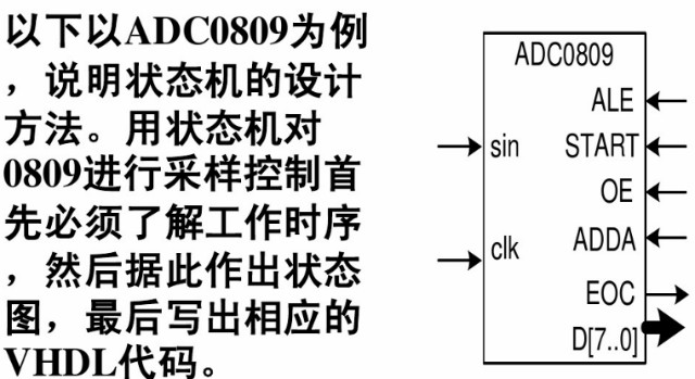
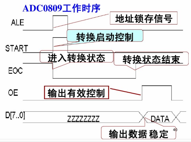
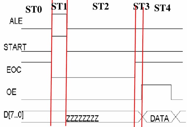
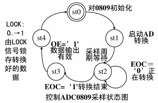
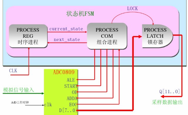
AD0809状态设计